Worthington Foundation Construction I
In this section you'll get to see what we actually did in the process of constructing the foundation for this engine. This phase of the project was started in the fall of 2000 when the hole was excavated for the foundation. Final planning and preparation was completed in the winter of 2000 / 2001 and actual construction began in the spring of 2001. The building of this foundation would span the entire summer with the final pour of concrete being completed in October 2001.
One thing you may notice as you study the construction pictures is the method we used to build the forms. Since we would be pouring 4 separate layers we wanted to construct forms that could be used from one pour to the next. For instance, the bottom pad was 15" thick and the one above it 14" thick. We constructed forms much the same way as you would frame the walls of a house. 2 x 4's in 8 foot lengths were used with studs spaced every 16" and covered on one side with plywood. Each of these sections would then be bolted together end to end with 4 x 4's posts used to support the corners. For the bottom 15" pour a 1" spacer was attached to one edge of all of the form sections. When we formed the 14" pour that came next the spacers were removed leaving the forms at the correct height. The plywood surface was sprayed with a water proofing chemical to prevent the concrete from sticking. This made the forms easy to remove after the concrete was set. The water proofing was applied to the forms before each pour was performed to ensure they would still be easy to remove. All forms built for this project followed the same method and we can say that they worked very well.
![]() |
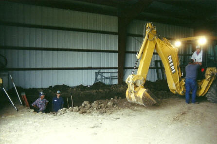
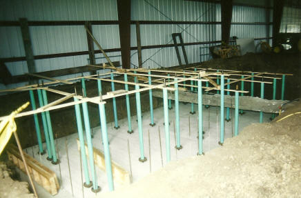
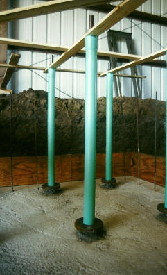
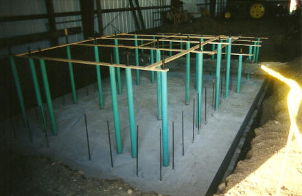
Here is where it all began, with the excavation of the hole to build the foundation in. Waverly Well & Plumbing generously donated the service of performing the excavation for this project. When completed the hole measured approximately 16' by 30' and was about 5 1/2' deep. |
Here you can see how the forms and rebar appeared for the bottom layer pour. This bottom slab would be the the reference upon which the rest of the foundation would be built. The first layer was 15" thick and approximately 16' by 28' in width and length. Included in the middle of this layer was a mesh of #6 (3/4" diameter) reinforcing bar in a 12" spaced grid. Around the perimeter was a series of vertical #4 (1/2" diameter) reinforcing bar to help tie all layers of the foundation together and reinforce the outer edges. |
![]() |
![]() |
The big day for the first pour finally arrived in the spring of 2001. This pour required approximately 21 cubic yards of concrete. Shown here is the concrete from the first truck load being vibrated into place. Vibrating the concrete helps remove air bubbles resulting in a much stronger set. |
To the right you can see the final result of the first pour. The outer edge of the concrete was troweled smooth because the forms for the next pour would rest on this edge. The middle part of the pour was purposefully left rough so that the next layer would be able to bond to it. The bar you see passing through the top of the screen is a reinforcing "tie bar" that is part of the foundation for the building. An allowance was made in the engine foundation design to be built around this so it could still perform its function. |
![]() |
![]() |
Here you can see one of the most challenging parts of the project - the positioning of the base bolts for the engine. There are 34 bolts in all including 18 1 1/4" diameter and 16 1 1/2" diameter. To position the bolts so they would match the engine a wooden template was made as you see here. The tops of the bolts passed through these boards and were secured by nuts on the top. This made the entire bolt, bolt casing, and anchor plate assembly rigid. The template was held in position by attaching it to the outside walls of the building. At this point the forms from the first pour are ready to be assembled into position around the perimeter of the base. Each of these bolts was made from discarded well rod. These can be purchased for a very reasonable price from most well drilling businesses and then cut to the required length and threaded. |
Here is a closer view of the bolt and casing assemblies. At the bottom of each you can see the steel anchor plate which will be buried in the concrete. Under these is a nut that secures the bolts to the anchor plates. You will also notice that each bolt is housed in PVC drain pipe. The reason for this is explained in the "Stationary Steam Engine Foundation Design" section of this site. The bottoms of the bolts were made rigid to the bottom slab by placing a small amount of concrete around them, in essence gluing them to the slab. This guaranteed they would not move as the next level of concrete was poured around them. |
![]() |
![]() |
Here is an example of the way the forms from the first pour were used again for the second pour. This pour was 4" smaller on all sides. This is part of the spread footing design to have a larger surface area on the bottom of the base to carry the weight. Another benefit of this was that the forms could lay on the concrete from the previous pour. Here you can see how the forms were set so they overlapped in the corners since they were still the same length for the larger first pour. |
Here is the foundation as it appeared after the second pour was completed. The bottoms of the bolts and their anchor plates and now firmly buried in the concrete. The bracing for the bolt template could now be removed from the building but was left on the tops of the bolts to ensure they and the bolt casings remained rigid. Dirt was now filled in around the edge of this pour and preparations for the largest and most complex of the pours was begun. |
![]() |
For more of the construction series of the Worthington foundation click here
|