 |
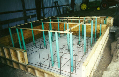
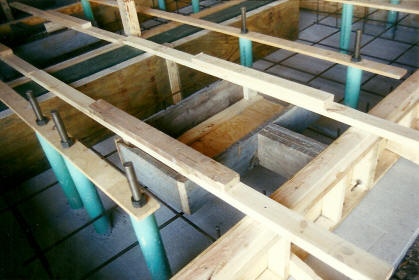
Here
the forms and rebar are being prepared for the third pour of
concrete. This 36" deep pour would be the most complex of the
project. You can see how the forms for the first 2 pours were used
once again. They are seen here as the bottom layer in the near
part of the photo with other form sections placed on top of them to make
the total 36" depth. The space in the center where the rebar
does not pass through is where a section of internal forms will be
placed to make the flywheel "pit". |
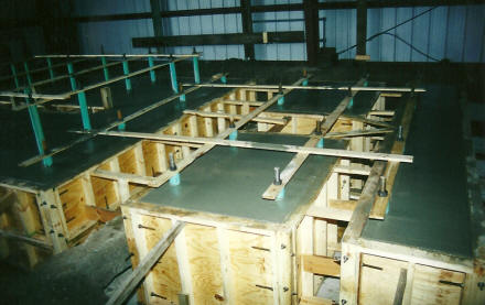
| This
photo shows the construction of the forms and foundation under the
cylinder end of the engine. You can see that this third pour was
actually done in four sections. The spaces that run from the front
to the back in this photo are where pipes for the engine will be.
In the passage to the left will be the steam line between the cylinders
and the steam exhaust line from the engine. The passage to the
right is for the pipes connecting to the air cylinders. |
 |
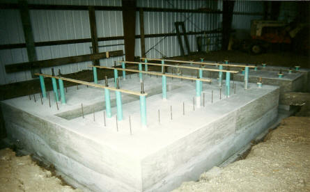 |
Shown
here is the result of the third pour of concrete after the forms were
removed. You can now clearly see the flywheel pit in the middle of
the picture. With this level completed the foundation finally
reached the level of the floor in the building. |
| The
fourth and final pour was for a raised section only under the crankshaft end
of the engine. We were able to determine why the original
foundation was constructed this way. The extra concrete under this
end of the engine was intended to balance the weight with the very heavy
cylinder end of the engine. Once again the forms from the first
two pours were used again with spacers attached to the top to achieve
the proper depth. |
 |
 |
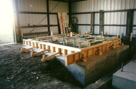
Here
you can see the forms for the flywheel pit reinstalled so it could be
extended through this final level (shown in the upper left of the
photo). Additionally, you will notice the box in the center to
leave a depression in this top level. This is to accommodate
"bulges" in the bottom of the the crank frame pieces of the
engine. These bulges are where the throw of the crankshaft
is. Another benefit of this design is that when the grout is
filled in under the pieces they will be even more rigidly attached to
the top of the foundation. |
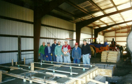
| In
October 2001 the final pour was completed. This was a proud moment
for the volunteers on hand for this big day! |
 |
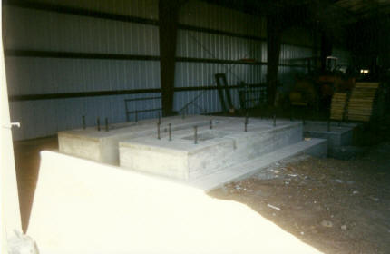 |
Shown
here is the completed foundation ready to accept the Worthington engine. |