Worthington Compressor Reconstruction V
Besides the installation of the steam pipe between the low and high pressure steam cylinders, the other highlight of 2009 was finally installing the flywheel dogbones.
|
|
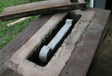
At this point, the time finally arrived to install the dogbones into the flywheel. The installation process is fairly simple, requiring each dogbone to be heated enough so that it will expand in length and fit into the pockets in the flywheel. Seen here is the forge we were able to borrow, with one of the dogbones inside ready to be heated. |
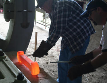
| After heating and carefully removing the dogbone from the forge, the next step was to install two pieces of ready-rod into holes we had drilled and tapped. This was a great help in handling the dogbone while it was this hot - it's interesting to imagine that the original engine builders installed the dogbones without this feature! |
|
|
|
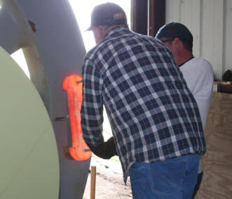
Here the dogbone is placed into the flywheel pocket. In all but one case, they fit fairly easily. However, one had to removed and reheated because it would not fit properly even with the help of a sledgehammer. Up to that point we had assumed they were not individually fit to each pocket, but this turned into a learning moment! |
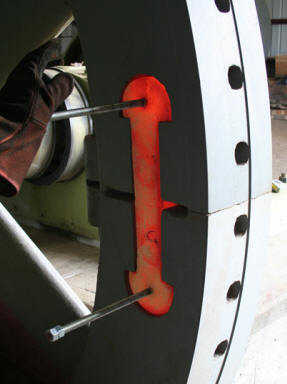
| With the dogbone fully seated into the pocket, all that's left to be done is to let it cool, shrink, and apply the many tons of force needed to hold the flywheel together. |
|
|
|
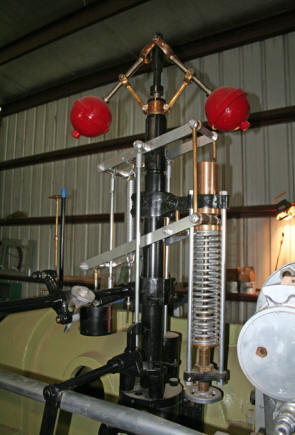
Towards the end of 2009, the unique speed / air pressure governor was also completed and reassembled. In normal operation, the engine was usually controlled by the small air cylinder at the right, above the large spring in direct response to the discharge air pressure. The fly-balls only controlled the engine when it was running at full speed under high air demands. |
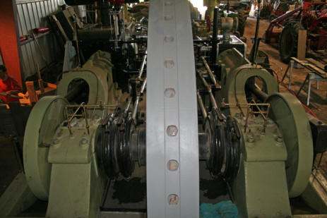
| Also wrapping up work toward the end of 2009, was the installation of the valve eccentrics, seen here on either side of the flywheel on the crankshaft. Slight differences in the placement of the engine base pieces made it necessary to create some different shims and spacers for proper alignment of the valve links. |
|
|
|
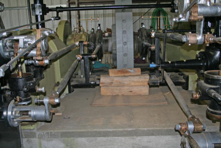
Shown here is another view of the re-installed eccentrics, intermediate rocker arms, and valve links. |
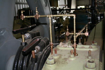
| Here you can see the beginning of the re-installation of the many lubricating oil lines, in this case for one of the main bearings and eccentrics. With most of the piping was in a semi-disassembled state and laying in a pile to start with, this has been not unlike putting together a jigsaw puzzle! |
|
For more of the reconstruction series of the Worthington click here