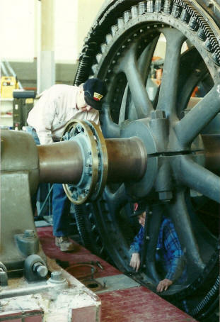
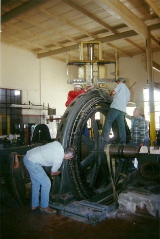
| The first work to be performed was disassembly of the generator. This included removing all of the rotating field coils which can be seen here on the outside of the rotor wheel. This was necessary because even though this wheel had a split hub, the outer rim could not be split. The coils were removed to keep weight at a minimum since the crankshaft and rotor would have to be moved as one assembly. On this weekend the valve and governor link rods were also removed, as well as the separate belt driven exciter. |
 |
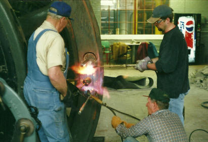 |
Shown here is the method required for removing the dogbones from the flywheel. The dogbones are used at the joint between each half of the flywheel to lock them together. They are made from steel and are heated and allowed to shrink in their flywheel pockets. To remove them it is necessary to heat them again until they are expanded enough for removal. Heating required 3 torches and approximately 15 minutes of time each before they could be removed. |
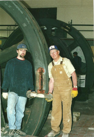
| Shown here is one of the dogbones after removal. The cross section of the dogbones were approximately 2 1/4" square. After the dogbones cooled they were measure to compare their length to that of the pocket. The difference was about 1/4". This translates into many tons of clamping force when the dogbones are installed with this amount of stretch. The bolts securing the hub of the flywheel to the crankshaft were also heated to removal. Even with heating, it was still required to use a sledge hammer and hammer wrench to loosen the bolts. |
 |
|
Work continued with many other tasks being performed. The bearing caps were removed from both the main and outboard bearings, the connecting rod disconnected, the dashpots removed, and any remaining piping and mechanical linkages also disassembled. Finally the big day arrived when the large pieces of both the Camp Creek and Clay Center engines would begin to be removed as shown below.
|
|
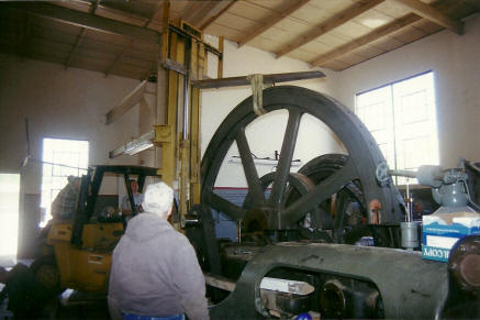 |
Heavy disassembly of the engines was accomplished by using 2 large forklifts. Here you can see the upper half of the flywheel for the Camp Creek engine being removed. This was a delicate operation since the weight of this piece was nearly at the limit of the forklift being used. |
| The next piece to be removed was the top half of the generator. |
 |
 |
With the top half of the flywheel and generator removed, it was now time for the single most difficult piece to handle to be lifted out: the crankshaft and generator rotor assembly. To accomplish this a forklift was used on each end of the shaft to lift it away from the engine. Once clear of the engine both forklifts had to move the shaft together away from the engine and toward the door at the end of the room. After this all other pieces of the engine seemed easy to remove by comparison! |
|
Click here or follow the "Back / Previous Page" link below to see the remaining Allis removal story.
|
|