Worthington Foundation Side Elevation |
Worthington Foundation Planning & Design
To say the least, this was a very challenging part of the project. The original foundation and erection drawings had been lost over the years. Our only choice was to measure and examine the original foundation that still existed in the Havelock shops power plant. From these measurements a set of drawings would have to be made for the foundation we would construct for the engine. Several trips were made to the original foundation to measure and double check all dimensions so the proper layout would be achieved. However, there would be a major difference in the base we constructed compared to the one originally used. The engine was originally installed in a power house which had a full basement under it and all of the other equipment. Because of this the engine sat on what could best be described as a tower of concrete. Of course, we would not be installing a full basement under the engine for our display. Therefore we had the dimensional data for the top of the base but needed to design a proper foundation for the part you don't see - the part buried in the soil.
At this time I was referred to a book that had been used in constructing other engines at other shows. The book is part of a power plant engineering set called "Power Plant Practice". This set of books was published by Mc-Graw Hill in the 1920's and edited by Terrell Croft. In this set is a volume titled "Machinery Foundations and Erection". This book was an extremely valuable resource as it covers all manner of heavy machinery foundation design and applications for engines and equipment of the time. Details of the design considerations can be seen in the "Stationary Steam Engine Foundation Design" section of this site.
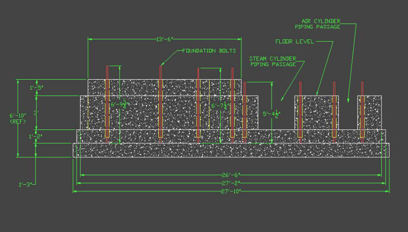
The Foundation shown below was the result of the design process. In the side elevation the crankshaft and flywheel would be to the left and the steam and air cylinders to the right. You will notice that there are several levels which get progressively larger in length and width toward the bottom. This was done to achieve the proper surface area on the bottom of the base so a safe soil pressure was maintained. Each of these levels also represents a separate pour of concrete during the construction process. In all, there are nearly 80 cubic yards of concrete in this design.
|
Worthington Foundation Side Elevation |
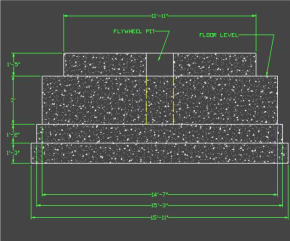
Worthington Foundation Crankshaft End Elevation |
Another crucial drawing that had to be prepared was for the foundation bolt layout. After the pad at the bottom of the foundation is poured it is then necessary to place the bolts in the proper position to accept the engine. Once the bolts are placed the rest of the concrete in the foundation is poured around them so that the majority of the mass of the foundation will anchor them. The drawing below shows the necessary bolt spacing required to correspond with the engine. From this drawing a wooden template was constructed to hold the bolts in position while the remaining concrete was poured. The process for achieving this is shown in the Worthington foundation construction section.
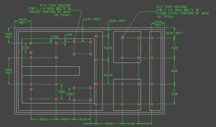
Worthington Foundation Top - Bolt Layout |