 |
 |
Stationary Steam Engine Foundation Design
As I have searched the internet and steam hobby magazines I have noticed that there isn't much in the way of detailed information concerning the design of large antique engine foundations. It is my hope that the information presented here will help give a better understanding of the special considerations required when designing a proper foundation for these types of machines. The information presented here is the result of our experiences in designing the foundation for our first large engine project, the Worthington steam air compressor. The original erection drawings had been lost long ago so new ones had to be prepared. We were able to measure the top of the original foundation for the proper bolt spacing and floor level dimensions but we had to design all of the foundation features below the floor. For photos and a detailed description of the construction of the Worthington foundation please visit the "Worthington Steam Air Compressor" section of the site.
Design Criteria:
We have relied heavily on a historical engineering book for the design of the Worthington foundation. The particular book is the volume titled "Machinery Foundations and Erection" from a series titled "Power Plant Practice". This set of books was published in the 1920's by Mc-Graw Hill and edited by Terrell Croft. The book is extremely well written with a clear and practical approach to this type of project.
Besides all of the specifics the book provides, there were three simple principles that should be followed when designing a foundation for engines such as these:
| 1. The depth of the foundation must be sufficient so that the bottom rests below the frost line of the soil where it is to be built. Of course, the depth must also be great enough to accommodate all features of the engine that may extend below floor level as well. |
| 2. The total weight, or mass of the foundation should also be between 3 and 5 times the weight of the engine it will support. With this type of engine there is a tremendous amount of reciprocating mass due to the size of the pistons and connecting rods. In order to prevent the engine from trying to move or "rock" the foundation the mass of the foundation must be very large. This also helps to dampen any vibrations the engine produces. |
| 3. The surface area of the bottom of the foundation must also be large enough so that at no point is the stable soil pressure exceeded. This is critical to ensure that the foundation will remain firm and no settling will occur. |
Another interesting aspect of foundations for these engines is the way the engines are attached. There are two elements that work together to accomplish this. First are the many bolts placed in the foundation that attach to the engine. Second is the use of concrete grout which is placed in a space between the engine and the foundation.
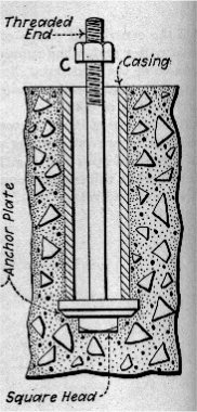
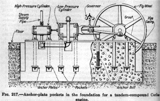
The bolts are secured as near to the bottom of the foundation as possible by means of an anchor plate and nut (or similar arrangement). The bolts are set in place before the concrete is poured so that the anchor plate will be buried in the concrete to secure the bolts. From the anchor plate to the top of the foundation the bolts are housed in tubes so there is a space around them in the concrete. There are two reasons for these tubes to be used. First, the bolts will remain flexible within the foundation so it will be possible to move and align the pieces of the engine as it is assembled. Second, this prevents any horizontal stresses from being transmitted to the base by the engine. Stresses such as this could pry on the foundation and cause it to crack. Illustrations of a foundation base bolt and an example of an engine, foundation, and bolts are shown below. The relative size of an engine foundation and the engine it supports can also be seen.
 |
 |
|
These illustrations are from the "Machinery Foundations and Erection" volume of "Power Plant Practice" mentioned earlier |
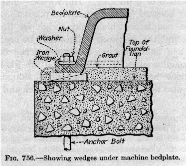
As mentioned before, concrete grout is also used to secure the engine to the foundation. This serves two purposes. First, when the engine is assembled it is aligned and leveled on a series of shims and wedges. This leaves an open air space between the bottom of the engine and the top of the foundation. Second, with the bolts securing the engine to the foundation in the vertical direction the grout is used to essentially "glue" the engine and prevent its movement in the horizontal direction. By doing this the horizontal stresses are applied to nearly the entire top surface of the foundation instead of relying on the bolts to do this at concentrated points. Below is an illustration from "Machinery Foundations and Erection" showing the relationship of an engine frame piece, foundation, and placement of the grout.
 |